
AVL Tree Rotations Explained
A step-by-step guide to LL, RR, LR, and RL rotations — the foundational pointer maneuvers that keep AVL trees strictly balanced in O(1) time.
Akshay Karande
Sep 20, 2026
The Need for Discipline
A standard Binary Search Tree offers O(log n) performance for search, insertion, and deletion. But this efficiency is fragile. Insert items in sequential order, and the tree silently collapses into a linked list, degrading every lookup to a sluggish O(n). In 1962, Soviet mathematicians Georgy Adelson-Velsky and Evgenii Landis introduced the first self-balancing binary search tree named AVL Tree.
Rather than allowing height to drift with incoming data, an AVL tree enforces a strict structural discipline after every modification. The engine behind that discipline is the tree rotation — an elegant, constant-time geometric transformation that alters subtree heights while leaving binary search order completely untouched.
Measuring Imbalance
To maintain balance, every node in an AVL tree keeps track of its height — the length of the longest downward path to a leaf. From this height, we derive each node's Balance Factor (BF):
BalanceFactor(node) = height(node.left) - height(node.right)
In a healthy AVL tree, the AVL Invariant dictates that for every node:
BalanceFactor(node) ∈ {-1, 0, +1}- BF = 0: Both subtrees have identical height. The node is in perfect equilibrium.
- BF = +1: The left subtree is taller by one level. Acceptable and valid.
- BF = -1: The right subtree is taller by one level. Acceptable and valid.
- BF = +2 or -2: The balance threshold has been breached. The node is critically unbalanced, and the tree must perform a rotation to restore order.
Unlike a Red-Black Tree, which tolerates looser structural variation (allowing one branch to be up to twice as long as another), the AVL tree will not tolerate a height gap greater than 1.
The BST Invariant
How can we reshape a tree without scrambling the order of its data? Recall that for any node X in a BST:
keys(left subtree) < key(X) < keys(right subtree)
A tree rotation is a local pointer exchange between a parent node and one of its children. During the rotation:
- The child moves up to assume the parent's former position.
- The parent moves down to become a child of that node.
- The "orphan" middle subtree (the child's inner branch) is handed over to the former parent.
Because every element in that transferred subtree lies between the parent and child values, the BST invariant is flawlessly preserved. Crucially, this operation touches only 3 to 5 pointers and runs in O(1) constant time.
The Four Imbalance Cases
When an insertion or deletion pushes a node's balance factor to +2 or -2, the imbalance originates from one of four directional configurations. We classify each case by the direction from the unbalanced node (Z) toward the taller child (Y), and from Y toward its taller child:
Case 1: Left-Left (LL) Imbalance
Node Z has BF = +2 and its left child Y has BF ≥ 0. The excess height lies entirely along the outer-left path (Left subtree of Left child). Perform a single Right Rotation at node Z. Node Y becomes the new subtree root, Z becomes Y's right child, and Y's right subtree (T2) attaches as Z's new left subtree.
Before Rotation (LL Imbalance at Z):

            Z (+2)
           /      \
         Y (+1)    T3
        /      \
      X (0)     T2
     /   \
   T0     T1

After Right Rotation at Z:

            Y (0)
          /       \
        X (0)      Z (0)
       /   \      /    \
     T0     T1   T2     T3

Key Pointer Shifts:
1. Z.left = Y.right  (T2 adopts Z as its parent)
2. Y.right = Z       (Z becomes Y's right child)
3. Y adopts Z's old parent
Case 2: Right-Right (RR) Imbalance
Node Z has BF = -2 and its right child Y has BF ≤ 0. The excess height is entirely along the outer-right path (Right subtree of Right child). The mirror image of the LL case. Perform a single Left Rotation at node Z. Node Y lifts up, Z drops to become Y's left child, and Y's left subtree (T2) attaches as Z's right subtree.
Before Rotation (RR Imbalance at Z):

            Z (-2)
           /     \
         T0       Y (-1)
                  /    \
                T1      X (0)
                       /     \
                     T2       T3

After Left Rotation at Z:

            Y (0)
          /       \
        Z (0)      X (0)
       /     \    /    \
      T0     T1  T2     T3

Key Pointer Shifts:
1. Z.right = Y.left  (T1 adopts Z as its parent)
2. Y.left = Z        (Z becomes Y's left child)
3. Y adopts Z's old parent
Case 3: Left-Right (LR) Imbalance
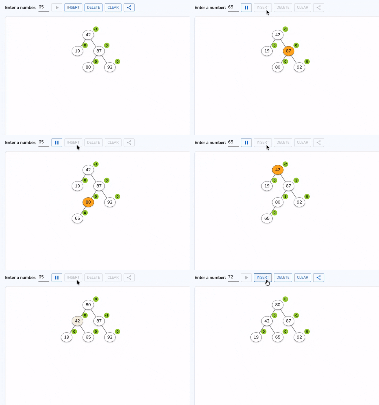
Node Z has BF = +2, but its left child Y has BF = -1. The excess weight is bent inward (Right child of Left child), forming a "zig-zag" or "elbow" shape. If you perform a naive right rotation at Z, the inner subtree simply swings over to the right branch, leaving Z with an RR imbalance. The tree remains broken.
This requires a double rotation in two distinct steps — Left Rotation at Y: Rotate child Y to the left. Grandchild X moves up to take Y's place, converting the zig-zag into a straight LL line. Right Rotation at Z: Perform a standard right rotation at Z. Node X now rises to become the subtree root.
Initial State (LR Imbalance at Z):

            Z (+2)
           /      \
         Y (-1)    T3
        /     \
      T0       X
              / \
            T1   T2

Step 1: Rotate Left at Child Y (converts LR → LL):

            Z (+2)
           /      \
         X (+1)    T3
        /     \
      Y        T2
     / \
   T0   T1

Step 2: Rotate Right at Grandparent Z (resolves balance):

            X (0)
          /      \
        Y         Z
       / \       / \
     T0   T1   T2   T3
What happens to the Balance Factors? Node X always ends with BF = 0. The final balance factors of Y and Z depend on where the newly inserted key landed inside X:
- If X had BF = +1 (insertion in T1): Y becomes 0, Z becomes -1.
- If X had BF = -1 (insertion in T2): Y becomes +1, Z becomes 0.
- If X had BF = 0 (X was the inserted node): Both Y and Z become 0.
Case 4: Right-Left (RL) Imbalance
Node Z has BF = -2, and its right child Y has BF = +1. The excess weight is bent inward on the right side (Left child of Right child). The mirror counterpart of the LR case — Right Rotation at Y: Rotate child Y to the right. Grandchild X moves up to take Y's place, transforming the structure into an RR case. Left Rotation at Z: Rotate grandparent Z to the left. Node X ascends to the root of the subtree.
Initial State (RL Imbalance at Z):

            Z (-2)
           /     \
         T0       Y (+1)
                  /    \
                X       T3
               / \
             T1   T2

Step 1: Rotate Right at Child Y (converts RL → RR):

            Z (-2)
           /     \
         T0       X (-1)
                  /    \
                T1      Y
                       / \
                     T2   T3

Step 2: Rotate Left at Grandparent Z (resolves balance):

            X (0)
          /      \
        Z         Y
       / \       / \
     T0   T1   T2   T3
The Universal Decision Matrix
When writing or tracing AVL logic, memorizing diagrams is unnecessary. The exact rotation required is determined entirely by the signs of two numbers: the balance factor of the unbalanced node (Z) and the balance factor of its taller child (Y):
Unbalanced Node (Z)   Child (Y)       Case   Action
───────────────────   ─────────────── ────   ──────────────────────────
BF(Z) > 1             BF(Y) >= 0      LL     RotateRight(Z)
BF(Z) > 1             BF(Y) < 0       LR     RotateLeft(Y) + RotateRight(Z)
BF(Z) < -1            BF(Y) <= 0      RR     RotateLeft(Z)
BF(Z) < -1            BF(Y) > 0       RL     RotateRight(Y) + RotateLeft(Z)
Insertion vs Deletion
Both insertions and deletions trigger rotations, but their structural aftermath differs profoundly.
Insertion: At Most One Rotation
When you insert a new key into an AVL tree, you traverse down to a leaf, add the node, and retrace back toward the root updating heights. The moment you encounter the lowest unbalanced ancestor (BF = ±2) and execute the appropriate rotation (single or double), the height of that entire subtree is restored to exactly what it was before the insertion occurred.
Because the subtree height does not grow beyond its pre-insertion level, no higher ancestors experience an increase in height. Therefore, an insertion never requires more than one rotation operation (at most two pointer-level rotations for LR/RL). Total rotation cost is O(1).
Deletion: Rotations May Cascade
Deletion is far more demanding. Removing a node (using the standard BST deletion rules) can shorten a subtree. When you rotate at an unbalanced ancestor to fix its balance factor, the height of that reconstructed subtree may decrease by 1 compared to its state before deletion.
This reduction in height can create an imbalance at the grandparent, which in turn requires another rotation, and so on. In the worst case, a single deletion can trigger rotations all the way up to the root — up to O(log n) rotations in total. This cascading potential is why write-intensive applications often prefer Red-Black Trees, where deletion fixup is guaranteed to require at most three rotations regardless of tree size.
Bringing It All Together
At their core, AVL rotations solve a fundamental challenge in computer science: maintaining peak search efficiency without the overhead of full tree reorganizations. By rearranging just a handful of pointers in O(1) time, these four maneuvers restore equilibrium locally while leaving the binary search order completely undisturbed.
💬 Discussion
to join the discussion
Curious to Learn More?
Hand-picked resources to deepen your understanding


© 2025 See Algorithms. Code licensed under MIT, content under CC BY-NC 4.0